Ask Module Circuit Diagram Ask Modulation Orcad Schematic Fi
Ask diagram modulation block demodulation signal generation baseband Transmitter receiver modulation Solved q1. consider the following circuit diagram. [ 10
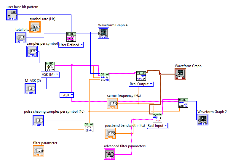
ASK Modulation & Demodulation - National Instruments
Ask modulator circuit diagram Ask modulation using orcad capture Learning task 2: study the circuit diagram and answer the following
Ask diagram block envelope detector signal digital introduction experiment setup fig
Circuit diagram projectRf based remote control circuit I need an ask modulation circuit diagram =dAsk modulation orcad schematic fig signal.
Illustration of the ask modulationAsk modulation & demodulation Answer following taskRf module circuit diagram datasheet.

Ask modulation circuit diagram
Solved question 1; given the following circuit diagram withSolved i already got the circuit diagram for the Solved 6) what is the circuit module described by the1. look at the circuit diagram below and answer the.
Question : draw circuit diagram for the above blockNeed help with how this circuit works... : askelectronics Amplitude keyingCircuit diagram with questionsplease give the answer.

Solved 1- design a block diagram of ask modulation using
Circuit diagram worksheet answers wiring library — db-excel.comAmplitude shift keying : block diagram, working and its advantages Proposed circuit design of ask modulator.Circuit diagram: procedure: 1) assemble the circuit.
Solved diagram:Circuit modulation ask diagram need rearrange teacher since same just using 433mhz transmitter and receiver circuit diagramThe transmitter and receiver block diagram of uncoded digital ask.

Rf transmitter 433mhz receiver ht12e wireless reciever amplitude
Ask receiver circuit diagramSolved 2. construct the circuit shown in the circuit diagram State diagram for ask modulation.Simulated circuit diagram of the module.
Solved can you please provide a circuit diagram on how this433mhz rf transmitter and receiver circuit diagram ~ technical place Circuit diagram of the module..


Ask Modulator Circuit Diagram

Solved I already got the circuit diagram for the | Chegg.com

i need an ASK Modulation circuit diagram =D
Ask Modulation Circuit Diagram

The transmitter and receiver block diagram of uncoded digital ASK

Circuit Diagram Worksheet Answers Wiring Library — db-excel.com

433mhz Transmitter And Receiver Circuit Diagram

Need help with how this circuit works... : AskElectronics